Time delay & integration (TDI) is a method of image capture built on the principle of line scanning, where a series of one-dimensional images are captured to generate an image by timing the sample motion and image slice capture by triggering. Although this technology has been around for decades, it has been typically associated with low-sensitivity applications, such as web inspection.
A new generation of cameras have combined the sensitivity of sCMOS with the speed of TDI to offer image capture of equal quality to area scan but with the potential for orders of magnitude quicker throughput. This is particularly evident in situations where imaging of large samples in low-light conditions is required. In this technical note, we outline how TDI scanning works, and compare the image capture time to a comparable large area scanning technique, tile & stitch imaging.
From line scanning to TDI
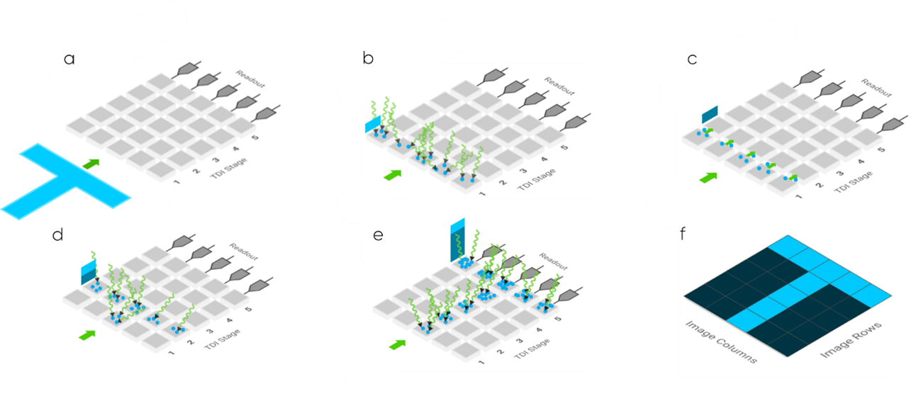
Figure 1: an animated example of image capture using TDI technology. A sample (blue T) is passed over a TDI image capture device (a column of 5 pixels, 5 TDI stages), and photoelectrons are captured in each stage and added to the signal level. A readout converts this to a digital image.
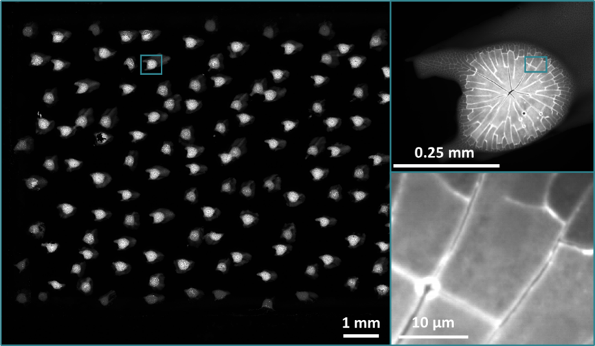
Figure 2: An image of a fluorescent sample captured using a Tucsen 9kTDI. Exposure 10 ms, capture time 10.1 s.
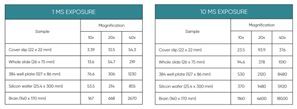
Table 1: Matrix of capture time of varying sample sizes (seconds) using a Tucsen 9kTDI camera on a Zaber MVR series motorized stage at 10, 20, and 40 x for 1 & 10 ms exposure time.
Line scan imaging is an imaging technique that uses a single line of pixels (referred to as a column, or stage) to take a slice of an image whilst a sample is in motion. Using electrical triggering mechanisms, a single 'slice' of an image is taken as the sample passes the sensor. By scaling the camera trigger rate to capture the image in step with sample motion and using a frame grabber to capture these images, they can be stitched together to reconstruct the image.
TDI imaging builds on this principle of image capture of a sample, however, uses multiple stages to increase the number of photoelectrons captured. As the sample passes each stage, more information is collected and added to the existing photoelectrons captured by earlier stages and shuffled in a similar process to CCD devices. As the sample passes over the final stage, the collected photoelectrons are sent to a readout, and the integrated signal across the range is used to generate an image slice. In Figure 1, image capture on a device with five TDI columns (stages) is shown.
1a: The image (a blue T) is introduced to the stage; the T is in motion as shown on the device.
1b: As the T passes the first stage, the TDI camera is triggered to accept photoelectrons which are captured by the pixels as they hit the first stage on the TDI sensor. Each column has a series of pixels that capture photoelectrons individually.
1c: These captured photoelectrons are shuffled to the second stage, where each column pushes its signal level to the next stage.
1d: In time with the movement of the sample one-pixel distance, a second set of photoelectrons are captured on stage two, and added to the previously captured ones, increasing the signal. In stage 1, a new set of photoelectrons are captured, corresponding to the next slice of image capture.
1e: The image capture processes described in stage 1d are repeated as the image moves past the sensor. This builds a signal from photoelectrons from the stages. The signal is passed into a readout, which converts the photoelectron signal into a digital readout.
1f: The digital readout is displayed as an image column by column. This allows for digital reconstruction of an image.
As the TDI device is capable of simultaneously passing photoelectrons from one stage to the next, and capturing new photoelectrons from the first stage whilst the sample is in motion, the image can be effectively infinite in the number of rows captured. The trigger rates, which determine the number of times image capture (fig 1a) occurs, can be on the order of hundreds of kHz.
In the example of Figure 2, a 29 x 17 mm microscope slide was captured in 10.1 seconds using a 5 µm pixel TDI camera. Even at significant zoom levels, the level of blur is minimal. This represents a huge advancement on previous generations of this technology.


For further detail, Table 1 shows representative imaging time for a series of common sample sizes at 10, 20, and 40 x zoom.
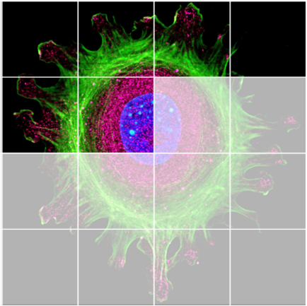
Figure 3: A slide of a human cell being captured by an area scan camera using tile & stitch imaging.
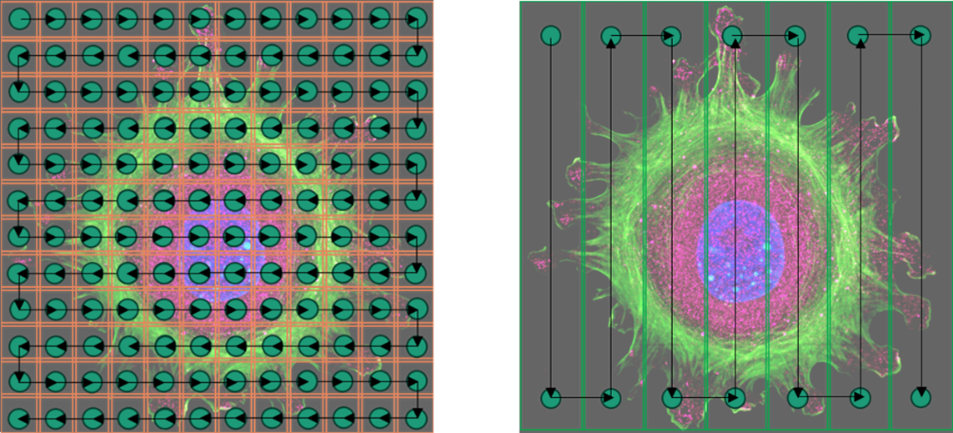
Figure 4: A scanning motif of the capture of a human cell under fluorescence showing tile and stitch (left) and TDI imaging (right).
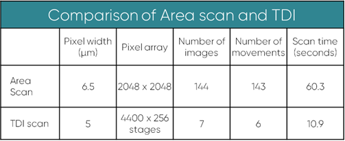
Table 2: Comparison of area scan and TDI imaging for a 15 x 15 mm sample with a 10x objective lens and 10 ms exposure time.
Area scan imaging
Area scan imaging in sCMOS cameras involves capturing an entire image simultaneously using a 2-dimensional array of pixels. Each pixel captures light, converting it to electrical signals for immediate processing and forming a complete image with high resolution and speed. The size of an image that can be captured in a single exposure is governed by the pixel size, the magnification, and the number of pixels in an array, per (1)
For a standard array, the field of view is given by (2)
In instances where a sample is too large for the field of view of a camera, an image can be constructed by separating the image into a grid of images of the size of the field of view. Capture of these images follows a pattern, where the stage will move to a position on the grid, the stage will settle, and then the image will capture. In rolling shutter cameras, there is an additional wait time whilst the shutter revolves. These images can be captured by moving the camera position and stitching them together. Figure 3 shows a large image of a human cell under fluorescence microscopy formed by stitching together 16 smaller images.
In general, resolving greater detail will require more images to be generated and stitched together in this way. One solution to this is to employ large format camera scanning, which has large sensors with a high pixel count, in tandem with specialized optics, allowing for a greater amount of detail to be captured.
Comparison between TDI and area scanning (Tile & Stitch)
For large-area scanning of samples, both Tile & Stitch and TDI scanning are appropriate solutions, however by selecting the best method, it is possible to reduce the time required to scan a sample significantly. This time saving is generated by the ability of TDI scanning to capture a moving sample; removing the delays associated with stage settling and rolling shutter timing associated with tile & stitch imaging.
Figure 3 compares the stops (green) and movements (black lines) required to capture an image of a human cell in both tile & stitch (left), and TDI (right) scanning. By removing the need to stop and realign the image in TDI imaging, it is possible to decrease imaging time significantly, providing exposure time is low <100 ms.
Table 2 shows a worked example of scanning between a 9k TDI and a standard sCMOS camera.
Whilst TDI offers fantastic potential for increased speed of image capture, there are nuances to the use of this technology. For high exposure times (>100 ms), the significance of the time lost to the move and settle aspects of area scan are reduced relative to exposure time. In such instances, area scan cameras may offer reduced scan times compared to TDI imaging. To see whether TDI technology can offer you benefits over your current setup, contact us for a comparison calculator.
Other applications
Many research questions require more information than a single image, such as multichannel or multifocus image acquisition.
Multichannel imaging in an area scan camera involves capturing images using multiple wavelengths simultaneously. These channels typically correspond to different wavelengths of light, such as red, green, and blue. Each channel captures specific wavelength or spectral information from the scene. The camera then combines these channels to generate a full-color or multispectral image, providing a more comprehensive view of the scene with distinct spectral details. In area scan cameras, this is achieved by discrete exposures, however, with TDI imaging, a splitter can be used to separate the sensor into multiple parts. Splitting a 9kTDI (45 mm) into 3 x 15.0 mm sensors will still be larger than a standard sensor (6.5 µm pixel width, 2048 pixels) width of 13.3 mm. Moreover, as TDI only requires illumination on the part of the sample being imaged, the scans can be cycled more quickly.
Another area where this may be the case is in multi-focus imaging. Multifocus imaging in area scan cameras involves capturing multiple images at different focus distances and blending them to create a composite image with the entire scene in sharp focus. It addresses varying distances in a scene by analyzing and combining in-focus regions from each image, resulting in a more detailed representation of an image. Again, by using a splitter to partition the TDI sensor into two (22.5 mm), or three (15.0 mm) pieces, it may be possible to acquire a multifocus image more quickly than an area scan equivalent. For higher order multifocus (z stacks of 6 or greater) however, area scan is likely to remain the fastest imaging technique.
Conclusions
This technical note outlines the differences between area scanning and TDI technology for large-area scanning. By merging line scanning and sCMOS sensitivity, TDI achieves fast, high-quality imaging without interruptions, surpassing traditional area scan methods like tile & stitch. Assess the advantages of using our online calculator, considering various assumptions outlined in this document. TDI stands as a powerful tool for efficient imaging with great potential for reducing imaging times in both standard and advanced imaging techniques. If you would like to see whether a TDI camera or area scan camera could match your application and improve your capture time, contact us today.

 23/10/10


