
 2025/09/24
One of the key questions in capturing details is how much of the imaging subject can you actually see? Achieving a high enough field of view can be vital in many applications – the aim could be to fit an entire imaging subject into one frame, see the largest population of multiple items for better statistics (for example, multiple cells), or include more context about the area around an imaging subject.
Understanding FOV is fundamental for anyone working with microscopes, industrial cameras, or other scientific imaging devices. This article will explore the concept of FOV, its role in imaging systems, the impact of lenses and sensors, common challenges, and practical tips to optimize imaging results.
What is Camera Field of View (FOV)?
The field of view (FOV) of a system can firstly be defined in object space. For microscopes, this means the size of images after magnification is applied. For lenses, similarly FOV can be measured at the focal plane, or as angular FOV. Alternatively, we can define FOV by the physical size of the cone or cylinder of light delivered to the camera sensor by the optical system, or that which is visible to the camera. This is determined by the physical size and capability of the camera sensor and optical components and does not consider magnification or focal length.
FOV can be expressed in two main ways:
1. Angular FOV – The angle covered by the camera’s lens, typically measured in degrees. This is common in wide-angle or telescopic applications.
2. Linear or Spatial FOV – The physical dimensions of the observable area, often measured in micrometers or millimeters, particularly in microscopy.
The field of view is limited by the lowest field of view component. When limited by the optical system, dark vignetting or unacceptable optical aberrations may be visible at the edges of a camera’s image. When limited by the camera sensor size, the image captured will only sample some fraction of the image delivered by the optical system.
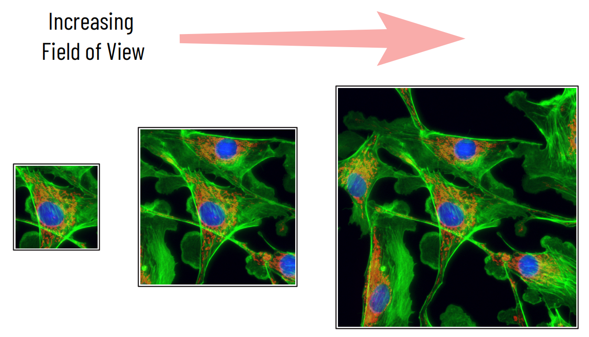
Figure 1: Increasing field of view
Sample shown is a multi-channel fluorescence microscopy image of BPAE cells.
Field of View limitations
In microscope systems, each component in the optical path, including objectives, filters, additional lenses, apertures, camera mounts and more, can all limit field of view.
Most microscopes specify their recommended maximum field of view using the ‘field number’. For the majority of older microscopes, this would be around 18mm. Modern microscopes can sometimes reach in excess of 30mm, with specialist optical components designed for larger fields of view.
Typical optical Components That Limit Field of View:
● Microscope objective: Some objective lenses, especially lower magnification lenses, may deliver more than the rated field number. However, the optical quality (including flatness of focus and lack of aberrations) is not guaranteed outside of this number, so typically degrades quickly towards the edges.
● Illumination: To achieve good image quality across a large field of view, illumination sources and optical paths that can deliver a large illumination area are required.
● Filters and internal components: Unless specifically designed for the larger FOV, many filters and other components are around 20mm in diameter, putting a hard limit on the field of view that can be delivered.
● Camera Mount: The camera mount can also place a limit on the field of view. The most common form of mount, C-mount, can deliver only up to 22mm FOV, while other options can deliver in excess of 40mm to large sensor cameras.
Object space FOV for microscopes
The field of view in object space, i.e., the amount of our imaging subject that is actually visible, can be calculated in x and y by the following formula:
Role of Lenses in Field of View
In microscopes, the objective performs the principal magnification, but there are often options for additional magnification or demagnification between the objective and the camera. These can be used to change camera pixel size to improve sensitivity (demagnifying, additional magnification < 1), or reduce pixel size to achieve optimal Nyquist sampling (additional magnification > 1).
They are also used to increase the FOV, or fit the microscope’s output to a smaller sensor camera – both through demagnification. The total magnification of the system is the product of the magnifications of each magnifying component.
Drawbacks of using extra magnification
It is worth treating additional magnification with caution, as each additional air/glass interface added to an optical system, of which each lens, of course, has two scatters or reflects up to 4% of the light that passes through it, meaning that only around 90%-95% of the light reaches the next optical element.
Further, microscope objectives are extensively designed and engineered to provide a high-quality aberration-free image, even out to the edges of the field of view. Additional magnification optics, on the other hand, may be significantly lower in quality. The effect of this will be most noticeable at the edges of the field of view – the exact areas that the lens was introduced to show, in the case of using additional optics to increase field of view. Where possible, the magnification should be set by the objective, and additional magnification lenses should be carefully considered.
Lens Field of View
As with microscopes, different lenses are designed to deliver different fields of view to the sensor, for different sensor sizes. As with microscope objectives, the limitation of field of view will likely be seen as a combination of hard limits (optical vignetting) and the introduction of aberrations towards the edges of the image. The difference between the image quality at the center and towards the edges of a lens can be greater than that for a microscope objective. The capability of a specific lens to meet your needs depends upon your application and may require experimental testing.
Focal length, focal plane and object space FOV for lenses
The object space field of view (i.e., how much of your imaging subject is in view) depends upon its distance from the lens, and the focal length of the lens. It can, therefore, make more sense to define image plane FOV in terms of angular FOV, which will still depend upon the focal length.
The angle of view of a lens in x and y is given by:
Note that when using calculators for this calculation, conversion from radians to degrees may be necessary.
Sensor Characteristics and Field of View
The camera sensor plays a pivotal role in determining the achievable FOV. The sensor size, pixel size, and aspect ratio of the camera all contribute to FOV.
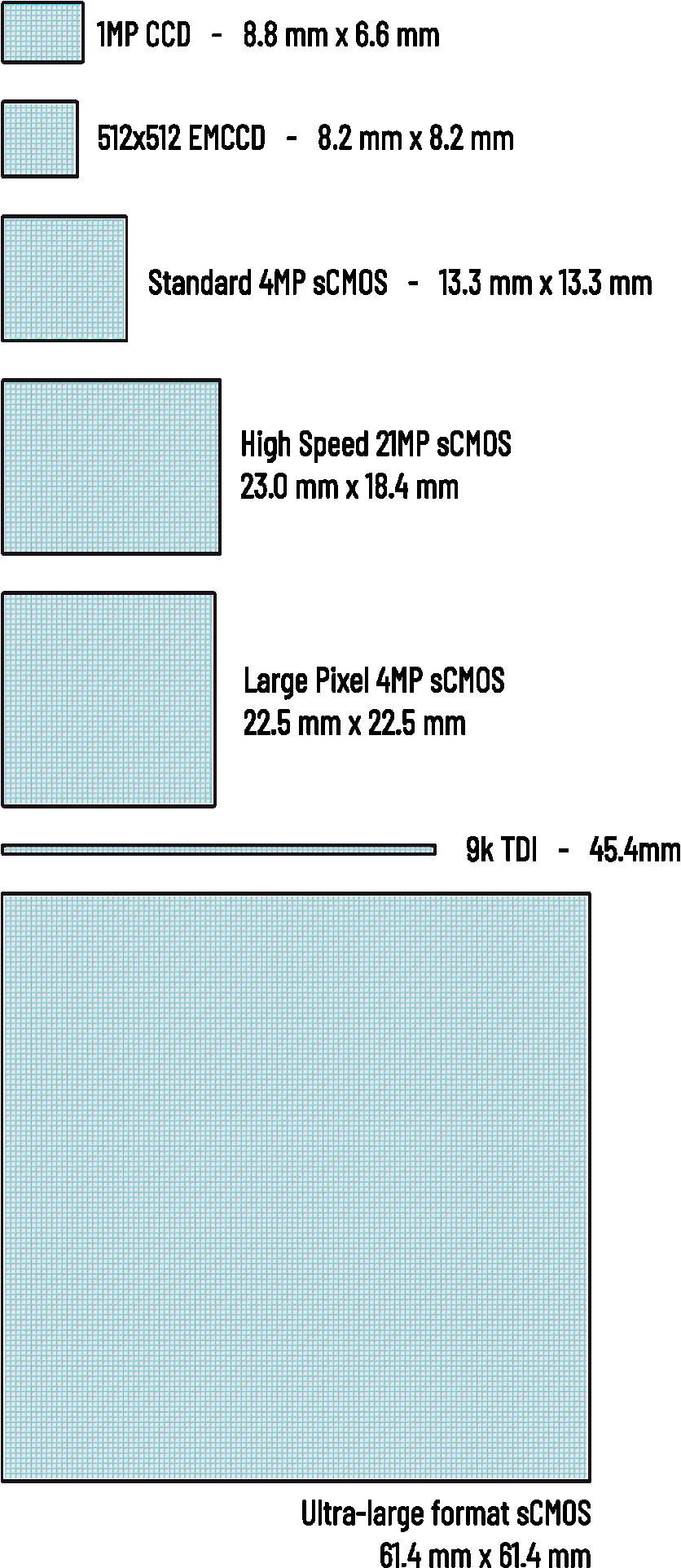
Figure 2: Sensor Sizes
The physical size of the camera sensor is a very important factor in determining the field of view of the complete system - providing that the optics used can utilize the entire sensor. Sensors shown to scale.
Sensor Size
The physical size of the camera sensor is a very important parameter in calculating the field of view. Many optical systems will be primarily limited by the camera FOV, determined by its sensor size.
Sensor size is usually provided both as a measurement in mm in x and y, and as a diagonal. It can also be calculated (as in the case for regions of interest (ROIs) by the pixel size multiplied by the number of pixels in x and y.
Previous generations of camera sensor technology, especially CCD and EMCCD sensors, could be as small as 10mm in diagonal or less. The field number of most microscopes is typically at least 18mm. This was a severe limitation. The introduction of CMOS cameras into scientific imaging has significantly increased sensor sizes, with 19mm diagonal sensors commonplace, and sensors up to 40mm in diameter or higher available.
Sensor Aspect Ratio
An important factor when considering the useful size of a sensor can be the aspect ratio of the sensor, i.e. the sensor width divided by height. While many scientific cameras use an aspect ratio of 1, implying a square sensor, rectangular sensors with aspect ratio > 1 are very common when the sensor is designed with video formats (4K, 8K) in mind.
The advantages of a lower aspect ratio sensor (such as a square sensor) are that they can more efficiently cover a circular aperture from an optical system. Also, for the same diagonal sensor size, a larger area will be covered. Which sensor geometry provides greater data throughput depends upon your optical system’s FOV, and your application needs.
How Camera Field of View Impacts Imaging Techniques
The FOV of a camera can dramatically influence the effectiveness of various scientific imaging techniques. It affects:
● Image Coverage: A narrow FOV might miss critical areas of the sample, while a wider FOV captures more but can dilute resolution. Striking the right balance between coverage and detail is crucial.
● Resolution and Detail: A smaller FOV can increase effective pixel density, which helps capture finer details and high-resolution images. On the other hand, a larger FOV may compromise pixel density and detail, so careful optimization is required to preserve both.
● Data Accuracy: Selecting the right FOV ensures that the imaging subject is captured in its entirety, which is essential for accurate measurement, quantification, and analysis. For example, in live-cell imaging, a too-small FOV may miss dynamic events happening at the field edges, leading to incomplete or biased data. Meanwhile, a very wide FOV could reduce image detail, making it difficult to identify smaller structures like organelles in cells.
Field of View in Microscopy
Microscopy is perhaps the most illustrative example of how FOV affects imaging outcomes. In microscopes:
● Objective Magnification: Higher magnification objectives reduce FOV but enhance detail. Lower magnifications increase FOV but reduce resolution.
● Sample Size Considerations: The FOV must be sufficient to observe the features of interest. For example, imaging an entire tissue sample requires a wider FOV, whereas studying cellular structures may necessitate a narrow FOV for higher resolution.
● Microscopy Techniques: FOV is critical in brightfield, confocal, and electron microscopy. Each technique imposes unique requirements on lens design, sensor choice, and illumination to ensure the desired coverage and resolution.
Field of View in Different Imaging Techniques
Beyond microscopy, FOV plays a significant role in many other scientific imaging applications:
● Industrial Imaging: Wide FOV cameras are used for machine vision, inspection of large components, and quality control. Narrow FOVs provide detailed inspection of small areas.
● Macroscopy / Macro Imaging: Useful in materials science, botany, and forensic analysis. FOV must balance coverage of larger samples with adequate detail.
● Astronomical Imaging: Telescopic cameras require extremely narrow FOVs for high-resolution imaging of distant celestial objects, while wide-field imaging captures larger portions of the sky.
In each case, the correct FOV ensures data accuracy, efficient observation, and optimal image quality.
Challenges and Limitations of Camera Field of View in Imaging
Despite advances in camera technology, FOV limitations persist in various imaging systems:
● Distortion: Wide FOV lenses may introduce barrel or pincushion distortion, affecting measurement accuracy.
● Vignetting: Uneven illumination across the FOV can lead to darkened edges.
● Trade-offs: Increasing FOV often reduces resolution and pixel density. Narrowing FOV enhances detail but may require multiple images to cover a large area.
● Sensor Limitations: Some sensors cannot fully capture the lens-projected FOV, causing cropping or reduced coverage.
Addressing these challenges requires careful selection of camera-sensor combinations, lens types, and imaging parameters. Calibration and post-processing corrections are often necessary to ensure accurate scientific data.
Common Mistakes & Troubleshooting
Optimizing FOV is not always straightforward. Common mistakes include:
● Selecting the wrong FOV for the task—using a wide FOV for high-resolution tasks, or a narrow FOV when broader coverage is required.
● Misalignment of optics and sensors, which can distort the captured image and reduce effective FOV.
● Neglecting sensor-lens compatibility, causing overshoot or undershoot of the expected image field.
Troubleshooting tips:
● Always calculate expected FOV before imaging.
● Match the lens and sensor carefully to avoid overshoot or undershoot.
● Use calibration slides or grids to verify FOV accuracy.
● For microscopy, ensure the objective, camera, and tube length are compatible.
Conclusion
The camera field of view is a fundamental concept in scientific imaging that affects every aspect of data acquisition, from coverage and resolution to image quality and measurement accuracy. Understanding how lenses, sensors, and imaging techniques interact to define FOV allows researchers, technicians, and engineers to optimize their imaging setups, minimize errors, and improve data reliability. Whether using sCMOS cameras, CMOS cameras, or microscopes, selecting the right FOV is crucial for capturing reliable, actionable data.
Tucsen Photonics Co., Ltd. All rights reserved. When citing, please acknowledge the source: www.tucsen.com


