
 2022/07/13
Time Delay Integration (TDI) is an imaging technique that pre-dates digital imaging – but that still provides tremendous advantages at the cutting edge of imaging today. There are two circumstances in which TDI cameras can shine – both when the imaging subject is in motion:
1 – The imaging subject is inherently in motion with a constant velocity, as in web inspection (such as scanning moving sheets of paper, plastic or fabric for defects and damage), assembly lines, or micro fluidics and fluid flows.
2 – Static imaging subjects that could be imaged by a camera moved from area to area, by either moving the subject or the camera. Examples include microscope slide scanning, materials inspection, flat panel inspection etc.
If either of these circumstances could apply to your imaging, this webpage will help you consider whether a switch from conventional 2-dimensional ‘area scan’ cameras to Line Scan TDI cameras might give your imaging a boost.
The problem with Area-Scan & Moving Targets
● Motion Blur
Some imaging subjects are in motion by necessity, for example in fluid flow or web inspection. In other applications, such as slide scanning and materials inspection, keeping the subject in motion can be considerably faster and more efficient than stopping motion for each acquired image. However, for area-scan cameras, if the imaging subject is in motion relative to the camera, this can present a challenge.

Motion blur distorting an image of a moving vehicle
In situations with limited illumination or where high image qualities are required, a long camera exposure time might be desired. However, the motion of the subject will spread its light over multiple camera pixels during the exposure, leading to ‘motion blur’. This can be minimised by keeping exposures very short –under the time it would take for a point on the subject to traverse a camera pixel. This is the unusually at the expense of dark, noisy, often unusable images.
● Stitching
Additionally, typically imaging large or continuous imaging subjects with area scan cameras requires the acquisition of multiple images, which are then stitched together. This stitching requires overlapping pixels between neighbouring images, reducing efficiency and increasing data storage and processing requirements.
● Uneven illumination
What’s more, the illumination will seldom be even enough to avoid issues and artefacts at the borders between stitched images. Also, to provide illumination over a large enough area for the area-scan camera with sufficient intensity often requires the use of high-power, high-cost DC light sources.
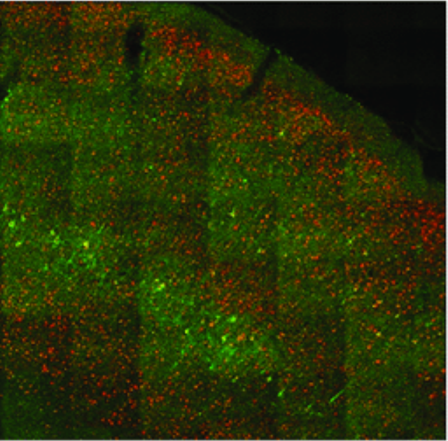
Uneven illumination in stitching a multi-image acquisition of a mouse brain. Image from Watson et al. 2017: http://dx.doi.org/10.1371/journal.pone.0180486
What is a TDI camera, and how does it help?
In conventional 2-dimensional area-scan cameras, there are three phases of acquiring an image: pixel reset, exposure, and readout. During the exposure, photons from the scene are detected, resulting in photoelectrons, which are stored in the camera pixels until the end of the exposure. The values from every pixel are then read out, and a 2D image formed. The pixels are then reset and all charges cleared to begin the next exposure.
However, as mentioned, if the imaging subject is moving relative to the camera, the light from the subject can spread over multiple pixels during this exposure, leading to motion blur. TDI cameras overcome this limitation using an innovative technique. This is demonstrated in [Animation 1].
● How TDI Cameras Work
TDI cameras operate in a fundamentally different way to area scan cameras. As the imaging subject moves across the camera during the exposure, the electronic charges making up the acquired image are moved too, staying in sync. During exposure, TDI cameras are able to shuffle all acquired charges from one row of pixels to the next, along the camera, synchronised with the motion of the imaging subject. As the subject moves across the camera, each row (known as a ‘TDI Stage’), provides a fresh opportunity to expose the camera to the subject, and accumulate signal.
Once a row of acquired charges reaches the end of the camera, only then are the values read out and stored as a 1-dimensional slice of the image. The 2-D image is formed by sticking together each successive slice of the image as the camera reads them. Each row of pixels in the resulting image tracks and images the same ‘slice’ of the imaging subject, meaning that despite the motion, there is no blur.
● 256x Longer Exposure
With TDI cameras, the effective exposure time of the image is given by the whole time it takes for a point on the subject to traverse every row of pixels, with up to 256 stages available on some TDI cameras. This means the available exposure time is effectively 256 times larger than an area-scan camera could achieve.
This can deliver either of two improvements, or a balance of both. Firstly, a significant boost in imaging speed can be achieved. Compared to an area scan camera, the imaging subject can be moving up to 256x faster while still capturing the same amount of signal, providing the line rate of the camera is fast enough to keep up.
On the other hand, if greater sensitivity is required, the longer exposure time could enable much higher quality images, lower illumination intensity, or both.
● Large data throughput without stitching
Since the TDI camera produces a 2-dimensional image from successive 1-dimensional slices, the resulting image can be as large as is required. While the number of pixels in the ‘horizontal’ direction is given by the width of the camera, for example 9072 pixels, the ‘vertical’ size of the image is unlimited, and simply determined by how long the camera is run. With line rates of up to 510kHz, this can deliver massive data throughput.
Combined with this, TDI cameras can offer very wide fields of view. For example, a 9072 pixel camera with 5µm pixels provides a horizontal field of view of 45mm with high resolution. To achieve the same imaging width with a 5µm pixel area scan camera would require up to three 4K cameras side by side.
● Improvements over line scan cameras
TDI cameras don’t just offer improvements over area scan cameras. Line scan cameras, which capture just a single line of pixels, also suffer from many of the same issues with illumination intensity and short exposures as area scan cameras.
Although like TDI cameras, line scan cameras offer more even illumination with a simpler setup, and avoid the need for image stitching, they can often require very intense illumination and/or slow subject movement to capture enough signal for a high-quality image. The longer exposures and faster subject speeds that TDI cameras enable means lower intensity, lower cost lighting can be used while improving imaging efficiency. For example, a production line may be able to move from high-cost, high power consumption halogen lights requiring DC power, to LED lighting.
How do TDI cameras work?
There are three common standards for how to achieve TDI imaging on a camera sensor.
● CCD TDI – CCD cameras are the oldest style of digital cameras. Due to their electronic design, achieving TDI behaviour on a CCD is comparatively very simple, with many camera sensors inherently able to operate in this way. TDI CCDs therefore have been in use for decades.
However, CCD technology has its limitations. The smallest pixel size commonly available for CCD TDI cameras is around 12µm x 12µm – this, along with small pixel counts, limits the cameras’ abilities to resolve fine details. What’s more, speed of acquisition is lower than other technologies, while read noise– a major limiting factor in low light imaging – is high. Power consumption is also high, which is a major factor in some applications. This led to the desire to create TDI cameras based on CMOS architecture.
● Early CMOS TDI: Voltage-domain and digital summing
CMOS cameras overcome many of the noise & speed limitations of CCD cameras, while using less power, and offering smaller pixel sizes. However, TDI behaviour was much harder to achieve on CMOS cameras, due to their pixel design. While CCDs physically move photoelectrons around from pixel to pixel to manage the sensor, CMOS cameras convert signals in photoelectrons to voltages in each pixel before readout.
TDI behaviour on a CMOS sensor has been explored since 2001, however, the challenge for how to handle the ‘accumulation’ of signal as exposure moves from one row to the next was significant. Two early methods for CMOS TDI still used in commercial cameras today are voltage-domain accumulation and digital summing TDI CMOS. In voltage-domain accumulation cameras, as each row of signal is acquired as the imaging subject moves past, the acquired voltage is added electronically to the total acquisition for that part of the image. Accumulating voltages in this way introduces additional noise for each extra TDI stage that is added, limiting the benefits of additional stages. Issues with linearity also challenge the use of these cameras for precise applications.
The second method is digital summing TDI. In this method, a CMOS camera is effectively running in area scan mode with a very short exposure matched to the time taken for the imaging subject to move across a single row of pixels. But, the rows from each successive frame are added together digitally in such a way that a TDI effect is delivered. As the entire camera must be read out for each row of pixels in the resulting image, this digital adding also adds the read noise for each row, and limits the speed of acquisition.
● The modern standard: charge-domain TDI CMOS, or CCD-on-CMOS TDI
The limitations of CMOS TDI above have been overcome recently through the introduction of charge-domain accumulation TDI CMOS, also known as CCD-on-CMOS TDI. The operation of these sensors is demonstrated in [Animation 1]. As the name implies, these sensors offer the CCD-like movement of charges from one pixel to the next, accumulating signal at each TDI stage through the addition of photoelectrons on the level of individual charges. This is effectively noise-free. However, the limitations of CCD TDI are overcome through the use of CMOS readout architecture, enabling the high speeds, low noise and low power consumption common to CMOS cameras.
TDI Specifications: what matters?
● Technology: The most important factor is what sensor technology is used as discussed above. Charge-domain CMOS TDI will deliver the best performance.
● TDI Stages: This is the number of rows of the sensor over which signal can be accumulated. The more TDI stages a camera has, the longer its effective exposure time can be. Or, the faster the imaging subject can move, providing the camera has sufficient line rate.
● Line Rate: How many rows the camera can read per second. This determines the maximum speed of movement that the camera can keep up with.
● Quantum Efficiency: This indicates the camera’s sensitivity to light at different wavelengths, given by the likelihood of an incident photon being detected and producing a photoelectron. Higher quantum efficiency can offer lower illumination strength, or faster operation while maintaining the same signal levels.
Additionally, cameras differ on the wavelength range at which good sensitivity can be achieved, with some cameras offering sensitivity all the way down to the ultra-violet (UV) end of the spectrum, at around 200nm wavelength.
● Read Noise: Read noise is the other significant factor in a camera’s sensitivity, determining the minimum signal that can be detected above the camera’s noise floor. With high read noise, dark features cannot be detected and dynamic range is severely reduced, meaning brighter illumination or longer exposure times & slower movement speeds must be used.
TDI Specifications: what matters?
Currently, TDI cameras are used for web inspection, electronics and manufacturing inspection, and other machine-vision applications. Alongside this are challenging low-light applications such as fluorescence imaging and slide scanning.
However, with the introduction of high-speed, low noise, high sensitivity TDI CMOS cameras, there is great potential for speed and efficiency increases in new applications that previously only used area-scan cameras. As we introduced at the start of the article, TDI cameras may be the best choice for achieving high speeds and high image qualities for either imaging subjects in constant motion already, or where the camera could be scanned across static imaging subjects.
For example, in a microscopy application, we could compare the theoretical acquisition speed of a 9K pixel, 256 stage TDI camera with 5 µm pixels to a 12MP camera area scan camera with 5 µm pixels. Let’s examine acquiring a 10 x 10 mm area with 20x magnification through moving the stage.
1. Using a 20x objective with the area scan camera would deliver a 1.02 x 0.77 mm imaging field of view.
2. With the TDI camera, a 10x objective with a 2x additional magnification could be used to overcome any limitation in the microscope field of view, to deliver a 2.3mm horizontal imaging field of view.
3. Assuming 2% pixel overlap between images for stitching purposes, 0.5 seconds to move the stage to a set location, and a 10ms exposure time, we can calculate the time the area scan camera would take. Similarly, we can calculate the time the TDI camera would take if the stage were kept in constant motion to scan in the Y direction, with the same exposure time per line.
4. In this case, the area scan camera would require 140 images to be acquired, with 63 seconds spent moving the stage. The TDI camera would acquire just 5 long images, with only 2 seconds spent moving the stage to the next column.
5. The total time spent acquiring the 10 x 10 mm area would be 64.4 seconds for the area scan camera, and just 9.9 seconds for the TDI camera.
If you would like to see whether a TDI camera could match your application and meet your needs, contact us today.


