 25/08/08
In industrial and scientific imaging, capturing fast-moving objects under low-light conditions presents a constant challenge. That’s where Time Delay Integration (TDI) cameras step in. TDI technology combines motion synchronization and multiple exposures to deliver exceptional sensitivity and image clarity, especially in high-speed environments.
What Is a TDI Camera?
A TDI camera is a specialized line scan camera that captures images of moving objects. Unlike standard area scan cameras that expose an entire frame at once, TDI cameras shift charge from one row of pixels to the next in synchronization with the object’s motion. Each pixel row accumulates light as the subject moves, effectively increasing exposure time and enhancing signal strength without introducing motion blur.
This charge integration dramatically boosts the signal-to-noise ratio (SNR), making TDI cameras ideal for high-speed or low-light applications.
How Does a TDI Camera Work?
The operation of a TDI camera is illustrated in Figure 1.
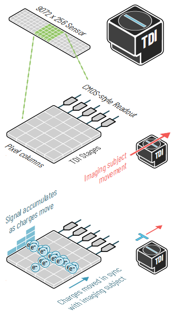
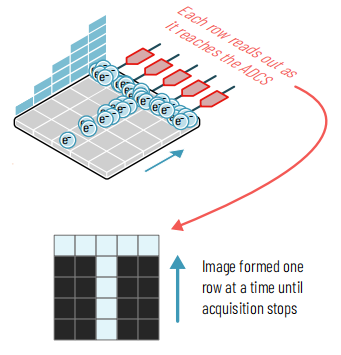
Figure 1: Operation of Time Delay Integration (TDI) sensors
NOTE: TDI cameras move acquired charges across multiple 'stages' in synchronization with a moving imaging subject. Each stage provides an additional chance to be exposed to light. Illustrated via a bright 'T' moving across a camera, with a 5-column by 5-stage segment of a TDI sensor. Tucsen Dhyana 9KTDI with hybrid CCD-style charge movement but CMOS-style parallel readout.
TDI cameras are effectively line scan cameras, with one important distinction: instead of one row of pixels acquiring data as cameras are scanned across an imaging subject, TDI cameras have multiple rows, known as 'stages', up to typically 256.
However, these rows don't form a 2-dimensional image like an area-scan camera. Instead, as a scanned imaging subject moves across the camera sensor, the detected photoelectrons within each pixel shuffle along to the next row in sync with the movement of the imaging subject, without yet being read out. Each additional row then provides an additional opportunity to expose the imaging subject to light. Only once an image slice reaches the final row of pixels of the sensor is that row then passed to the readout architecture for measurement.
Hence, despite multiple measurements taking place across the camera stages, only one instance of the camera read noise is introduced. A 256-stage TDI camera keeps the sample in view 256 times longer, and hence has 256 times longer exposure time than the equivalent line scan camera. An equivalent exposure time with an area scan camera would yield extreme motion blur, rendering the image useless.
When Can TDI Be Used?
TDI cameras are an excellent solution for any imaging application where the imaging subject is in motion relative to the camera, providing that motion is uniform across the camera’s view.
The applications of TDI imaging therefore include, on the one hand, all those of line scanning where 2-dimensional images are formed, while bringing greater speeds, much improved low-light sensitivity, better image quality, or all three at once. On the other hand, there are many imaging techniques that use area-scan cameras where TDI cameras can be used.
For high-sensitivity sCMOS TDI, 'tile and stitch' imaging in biological fluorescence microscopy can be performed using a nonstop scan of the stage in place of tiling. Or all TDI can be well suited to inspection applications. Another important application for TDI is imaging flow cytometry, where fluorescence images of cells are acquired as they pass a camera while flowing through a microfluidic channel.
Pros and Cons of sCMOS TDI
Pros
● Can capture 2-dimensional images of arbitrary size at high speed when scanning across an imaging subject.
● Multiple TDI stages, low noise, and high QE can lead to drastically higher sensitivity than line scan cameras.
● Very high readout speeds can be achieved, for example, up to 510,000Hz (lines per second), for a 9,072-pixel-wide image.
● Illumination only needs to be 1-dimensional and can require no flat-field or other corrections in the second (scanned) dimension. Additionally, longer exposure times compared to line scan can 'smooth out' flicker due to AC light sources.
● Moving images can be acquired without motion blur and with high speed and sensitivity.
● Scanning large areas can be drastically faster than area scan cameras.
● With advanced software or triggering setups, an 'area-scan-like' mode can provide an area-scan overview for focus and alignment.
Cons
● Still higher noise than conventional sCMOS cameras, meaning ultra-low-light applications are out of reach.
● Requires specialist setups with advanced triggering to synchronize the movement of the imaging subject with the scanning of the camera, very fine control over movement speed, or accurate prediction of speed to enable synchronization.
● As a new technology, few solutions currently exist for hardware and software implementation.
Low-light-capable sCMOS TDI
While TDI as an imaging technique predates digital imaging, and long ago surpassed line scan in performance, only in the last few years have TDI cameras gained the sensitivity required to reach the low-light applications that would ordinarily require the sensitivity of scientific-grade sCMOS cameras.
'sCMOS TDI' combines the CCD-style movement of charges across the sensor with sCMOS-style readout, with back-illuminated sensors available. Previous CCD-based or purely CMOS-based* TDI cameras had drastically slower readout, smaller pixel counts, fewer stages, and read noise between 30e- and >100e-. In contrast, sCMOS TDI such as the Tucsen Dhyana 9KTDI sCMOS camera offers read noise of 7.2e-, combined with higher quantum efficiency through back-illumination, enabling use of TDI in significantly lower light level applications than previously possible.
In many applications, the longer exposure times enabled by the TDI process can more than compensate for the increase in read noise compared to high-quality sCMOS area-scan cameras with read noise close to 1e-.
Common Applications of TDI Cameras
TDI cameras are found in many industries where precision and speed are equally critical:
● Semiconductor wafer inspection
● Flat panel display (FPD) testing
● Web inspection (paper, film, foil, textiles)
● X-ray scanning in medical diagnostics or baggage screening
● Slide and multi-well plate scanning in digital pathology
● Hyperspectral imaging in remote sensing or agriculture
● PCB and electronics inspection in SMT lines
These applications benefit from the enhanced contrast, speed, and clarity that TDI imaging provides under real-world constraints.
Example: Slide and Multi-Well Plate Scanning
As mentioned, one application with significant promise for sCMOS TDI cameras is stitching applications, including slide or multi-well plate scanning. Scanning large fluorescent or brightfield microscopy samples with 2-dimensional area cameras relies on stitching a grid of images formed from multiple movements of an XY microscope stage. Each image requires the stage to stop, settle, and then restart, along with any delay of the rolling shutter. TDI, on the other hand, can acquire images while the stage is in motion. The image is then formed from a small number of long 'strips', each covering the entire width of the sample. This can potentially lead to drastically higher acquisition speeds and data throughput in all stitching applications, depending on imaging conditions.
The speed at which the stage can move is inversely proportional to the total exposure time of the TDI camera, so short exposure times (1-20ms) offer the greatest improvement in imaging speed compared to area scan cameras, which can then lead to an order of magnitude or greater reduction in total acquisition time. For longer exposure times (e.g. > 100ms), area scan can usually retain a time advantage.
An example of a very large (2 Gigapixel) fluorescence microscopy image formed in just ten seconds is shown in Figure 2. An equivalent image formed with an area scan camera could be expected to take up to several minutes.
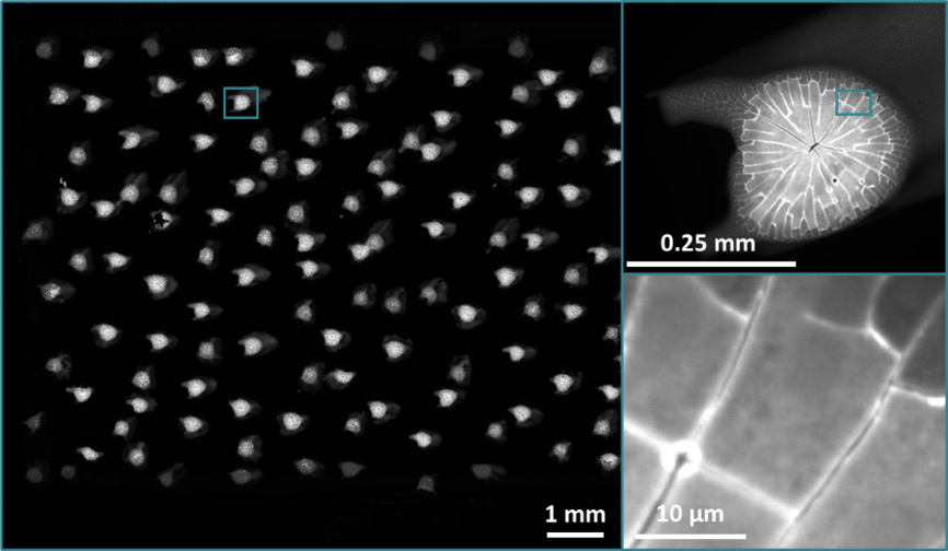
Figure 2: 2 Gigapixel image formed in 10 seconds through TDI scanning & stitching
NOTE: 10x magnification image acquired using the Tucsen Dhyana 9kTDI of highlighter pen dots viewed with fluorescence microscopy. Acquired in 10 seconds using 3.6 ms exposure time. Image dimensions: 30mm x 17mm, 58,000 x 34,160 pixels.
Synchronizing TDI
The synchronization of a TDI camera with the imaging subject (to within a few percent) is essential – velocity mismatch will lead to a 'motion blur' effect. This synchronization can be done two ways:
Predictive: Camera speed is set to match motion speed based on knowledge of sample movement speed, optics (magnification), and camera pixel size. Or trial and error.
Triggered: Many microscope stages, gantries and other equipment to move imaging subjects can include encoders that send a trigger pulse to the camera for a given movement distance. This allows the stage/gantry and camera to remain in sync irrespective of movement speed.
TDI Cameras vs. Line Scan and Area Scan Cameras
Here’s how TDI compares to other popular imaging technologies:
|
Feature |
TDI Camera |
Line Scan Camera |
Area Scan Camera |
|
Sensitivity |
Very High |
Medium |
Low to Medium |
|
Image Quality (motion) |
Excellent |
Good |
Blurred at high speeds |
|
Lighting Requirements |
Low |
Medium |
High |
|
Motion Compatibility |
Excellent (if synchronized) |
Good |
Poor |
|
Best For |
High-speed, low-light |
Fast-moving objects |
Static or slow scenes |
TDI is the clear choice when the scene is moving quickly and light levels are limited. Line scan is a step down in sensitivity, while area scan is better for simple or stationary setups.
Choosing the Right TDI Camera
When selecting a TDI camera, consider the following:
● Number of TDI stages: More stages increase SNR, but also cost and complexity.
● Sensor type: sCMOS is preferred for its speed and low noise; CCD may still be suitable for some legacy systems.
● Interface: Ensure compatibility with your system—Camera Link, CoaXPress, and 10GigE are common options, 100G CoF and 40G CoF have emerged as new trends.
● Spectral response: Choose between monochrome, color, or near-infrared (NIR) based on application needs.
● Synchronization options: Look for features like encoder inputs or external trigger support for better motion alignment.
If your application involves delicate biological samples, high-speed inspection, or low-light environments, sCMOS TDI is likely the right fit.
Conclusion
TDI cameras represent a powerful evolution in imaging technology, especially when built on sCMOS sensors. By combining motion synchronization with multi-line integration, they offer unmatched sensitivity and clarity for dynamic, low-light scenes.
Whether you're inspecting wafers, scanning slides, or performing high-speed inspections, understanding how TDI works can help you choose the best solution among scientific cameras for your imaging challenges.
FAQ
Can TDI cameras operate in area scan mode?
TDI cameras can create (very thin) 2-dimensional images in an 'area-scan-like' mode, achieved through a trick of sensor timing. This can be helpful for tasks like focus and alignment.
To begin an 'area-scan exposure', the sensor is first 'cleared' by advancing the TDI at least as many steps as the camera has stages, as fast as possible, then stopping. This is either achieved through software control, or hardware triggering, and is ideally performed in darkness. For example, a 256-stage camera should read at least 256 lines, then stop. This 256 lines of data is discarded.
While the camera is not being triggered or lines read out, the sensor behaves just like an area-scan sensor exposing an image.
The desired exposure time should then elapse with the camera idle, before again advancing the camera by at least its number of stages, reading out each line of the image just acquired. Once again, ideally this 'read out' phase should occur in darkness.
This technique can be repeated to provide a 'live preview' or sequence of area-scan images with minimal distortion and blurring from the TDI operation.
Tucsen Photonics Co., Ltd. All rights reserved. When citing, please acknowledge the source: www.tucsen.com


