
 2022/05/13
Readout noise is the uncertainty inherent in electronically measuring the number of photoelectrons the camera has detected. It’s typically specified in electrons (e⁻ RMS) and depends on readout speed, gain/conversion-gain mode, ADC configuration, and ROI—so it’s only comparable when conditions match.
In bright scenes, shot noise usually dominates and readout noise has little impact. In low-light imaging—weak fluorescence, astronomy, short-exposure high-speed work—readout noise can materially limit SNR and even detectability.
This guide shows how to interpret readout-noise specs, when it matters, which settings change it, and how to measure it reliably.
What Is Readout Noise?
Readout noise (often called read noise) is the random uncertainty introduced when a camera reads out an image—i.e., when the charge collected in each pixel is converted into a voltage and then digitized into a digital number (DN). Even with perfect optics and a stable scene, the readout electronics are never perfectly noiseless: amplifiers, reset and sampling circuitry, analog signal paths, and the analog-to-digital converter (ADC) can all contribute small fluctuations. The result is a per-pixel, per-frame random error added at readout.
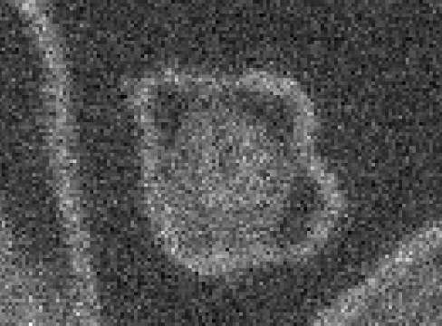
Figure 1: Read noise limited image
In this ultra-low-light regime, signal values are comparable to read noise, meaning read noise is the primary limiting factor to the SNR.
Because the sensor ultimately measures light as electrons, readout noise is most commonly specified in electrons (e⁻), typically as e⁻ RMS. Expressing noise in electrons makes it easier to compare performance across camera settings and models. (If you start from DN, converting to e⁻ requires the system conversion gain, e⁻/DN.) In modern scientific cameras, readout noise can be very low—often at the ~1–3 e⁻ RMS level in low-noise modes for low-light imaging—though the exact value depends on readout speed, gain / conversion-gain mode, ADC configuration, ROI, and temperature.
Typical values and why they vary
For many sCMOS cameras, read noise has become low enough that very small signals can be measured with good fidelity. Other sensor technologies and operating modes may show higher readout noise, especially when optimized for maximum frame rate. See Table 1 for some representative values.This is why it’s essential to compare read noise only under matched test conditions (mode, readout speed, gain, bit depth, ROI, etc.).
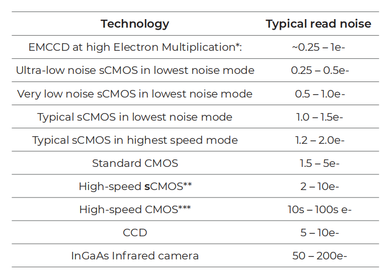
Table 1: Typical RMS read noise values for different scientific camera technologies
* EMCCDs have additional noise sources that reduce their sensitivity
** High-speed sCMOS such as the Tucsen Dhyana 2100 sCMOS camera
*** High-speed CMOS cameras are used both in scientific imaging and film for high-speed motion capture. These cameras cannot typically be used in low-light imaging due to their high noise burying low-light signals.
RMS vs Median read noise (and why some datasheets show two numbers)
In CMOS/sCMOS sensors, read noise can vary slightly from pixel to pixel, so it can be helpful to think of read noise as a distribution rather than a single value. Some cameras also exhibit a small “tail” of higher-noise pixels, where effects such as random telegraph noise (RTN) can be more pronounced.
To summarize that distribution, manufacturers may report a median (typical) read noise value, and sometimes an additional RMS figure that is more sensitive to higher-noise pixels. Definitions can vary by manufacturer, so the safest approach is to check the stated measurement method and conditions—especially when you are comparing cameras or selecting a mode for low-light work.
How to Read Readout Noise Specs?
A readout-noise value is only meaningful when it’s tied to how the camera was operated during the measurement. Mode, bit depth, readout speed, gain/conversion gain, and ROI can all change the number—so always compare specs under matched conditions.
Test conditions matter
A readout-noise number is only meaningful when it’s tied to the operating conditions used to measure it. The same camera can report different values depending on the readout mode and configuration, so “lower” is not automatically “better” unless you’re comparing like for like. Before you compare cameras—or even two modes on the same camera—look for these conditions in the datasheet table, footnotes, or performance plots:
● Readout speed / pixel rate (kHz–MHz): Faster readout typically increases readout noise.
Gain / conversion-gain mode (e.g., HCG/LCG): Changes e⁻/DN and can shift the reported noise value.
● ADC path / bit depth: Some cameras offer multiple ADC modes that affect noise and quantization behavior.
● ROI and readout channels: ROI can change how the sensor is read and may alter performance in some architectures.
● Temperature (if stated): Specs are often measured at a defined sensor temperature; always compare under similar conditions.
If a headline read-noise figure appears without mode/speed context, treat it as incomplete and find the detailed mode table or plot.
Typical vs Max / Median vs RMS: why you may see two numbers
Because of parallel readout architectures, most CMOS/sCMOS sensors show some pixel-to-pixel variation in readout noise, so it can be helpful to think of read noise as a distribution rather than a single value. That’s why some specification sheets report two numbers.
A median read-noise value indicates that 50% of pixels are at or below that figure, which often reflects “typical” performance. An additional RMS figure (when provided) is more sensitive to the spread of the distribution and can better capture the influence of higher-noise pixels in the tail. Since definitions can vary by manufacturer, always check the stated measurement conditions and reporting convention.
CMOS/sCMOS sensors can show pixel-to-pixel variation in readout noise, so read noise is better thought of as a distribution rather than a single value. To summarize that distribution, manufacturers may report:
● Typical / Median: A “typical pixel” figure that represents common performance in that mode.
● RMS (or sometimes a more conservative figure): A statistic that can be more sensitive to higher-noise pixels and better reflects the overall spread.
Not every vendor uses these terms in exactly the same way, so always check the stated definition and measurement method. When in doubt, compare cameras using values reported under the same statistic and conditions.
Camera mode examples (why one camera has multiple read-noise specs)
To make this concrete, consider the Tucsen Aries 6510 Ultimate Sensitivity sCMOS Camera. On its datasheet, readout noise is reported for multiple readout modes—because the camera can be operated at different bit depths and readout pipelines, and each has a different noise floor:
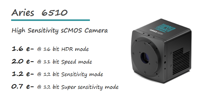
Figure 2: Aries 6510 readout noise
How to interpret this: these numbers are not contradictory—they describe different operating points of the same camera. A higher-speed pipeline (here, the Speed mode) typically prioritizes throughput and can show higher readout noise, while sensitivity-optimized pipelines can reduce the readout-noise floor. This is exactly why readout-noise specs should always be read together with the mode name and stated bit depth. When comparing cameras (or comparing a camera to a published value), make sure you are comparing the same mode, not just the lowest headline number.
When Readout Noise Matters?
Readout noise does not limit every experiment. Whether it matters comes down to a simple question: is readout noise a meaningful part of your total noise budget at the signal level you’re working with? In bright conditions, photon (shot) noise usually dominates. In low-signal conditions, readout noise can become the term that determines SNR—and sometimes whether faint structure is visible at all.
Read noise vs shot noise: a quick rule of thumb
Shot noise grows with signal as √N (where N is the number of detected photoelectrons). Readout noise is roughly a constant per pixel per frame for a given mode. This means:
 ● At high N, √N is large and readout noise contributes little.
● At low N, √N is small and readout noise can dominate.
A practical crossover point is when shot noise ≈ readout noise, i.e. when √N ≈ R. That corresponds to N ≈ R².
For example, if a mode has R = 2 e⁻ RMS, readout noise becomes significant when the signal is on the order of a few electrons to a few tens of electrons per pixel (since R2=4). If R = 10 e⁻, the crossover shifts to around 102=100 electrons per pixel.
A concrete SNR example (why it’s negligible in bright scenes)
Suppose a pixel contains 2,000 e⁻ of signal. Shot noise is √2000 ≈ 44.7 e⁻.
If readout noise is 10 e⁻, total noise (RMS) is:
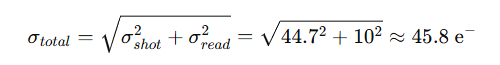
So SNR changes from 2000/44.7≈44.7 to 2000/45.8≈43.7—a small difference. In other words, at high signal levels, reducing readout noise rarely changes what you can see.
In high-light scenes where each pixel collects thousands of photoelectrons, readout noise becomes a small term in the total noise budget. For example, at 2,000 e⁻ of signal, adding 10 e⁻ of readout noise changes SNR by only a few percent—often imperceptible—whereas at tens of electrons per pixel, readout noise can materially limit SNR and visible detail.
When readout noise becomes a real limiter
Readout noise matters most when your experiment is signal-limited per frame—meaning each pixel collects only a small number of photoelectrons in a single exposure. In that regime, readout noise can dominate the noise budget, reduce SNR, and obscure faint structure.
Common application cues include:
● Weak fluorescence / low labeling density, especially with short exposures or fast time-lapse
● Single-molecule fluorescence and localization-based super-resolution, where signals can be only a few photons per emitter per frame
● Chemiluminescence imaging, where photon budgets are inherently low and readout noise can dominate
● High-speed functional imaging (voltage / membrane potential, fast calcium imaging), where short exposures reduce per-frame photon counts
● Photon-starved imaging workflows (e.g., very dim frames even if you plan to stack/average later)
As a practical check: if your typical per-pixel signal is in the hundreds to thousands of electrons per frame, readout noise is rarely dominant. If it’s in the tens of electrons or less, readout noise and mode choice can strongly influence image quality.
Conclusion
Readout noise is a mode-dependent, readout-chain-limited term—so the only meaningful comparisons are made under matched conditions (mode, readout speed, gain/conversion gain, ADC/bit depth, ROI). In bright scenes it’s often negligible, but in low-signal imaging it can materially limit SNR and detectability.
If you’d like a recommendation for your experiment, share your application details (signal level, exposure time, frame rate, wavelength, and target SNR). Our imaging specialists can suggest a Tucsen camera and the best readout mode to balance sensitivity, speed, and dynamic range.


